
● careerMay 2022 — Jul 2022
A cube-catching drone, in Brazil
- role
- Engineering intern (fourth-year internship)
- company
- LAMMI · Federal University of Paraná (UFPR)
- location
- Curitiba, Brazil
- tools
- Python
- Qt
- Raspberry Pi
- Blender
- Cleanflight
- links
Context
Three months, from 2 May to 28 July 2022, at the LAMMI, the magnetism, measurement and instrumentation laboratory of the Federal University of Paraná, in Curitiba. Founded in 2003, it works on electronic instrumentation, microelectronics and magnetism. Since 2017, it has welcomed students from Polytech Grenoble every year; this time there were three of us: Fabien Pagès, Ryan Hatil and me.

The D100 challenge
The internship prepares an inter-university competition, in Curitiba. The drone takes off from a zone A, flies 100 metres to fetch a 10 cm, 200 g cube waiting in a zone B, then brings it back. The pilot stays still, the drone only touches the ground in the zones, and the gripper must be designed by the team. The fastest wins, and one rule sums up the spirit: anything not forbidden is allowed.

Picking up the project
A drone already existed, built by previous years' teams, who had also tried to automate the landing with ROS, without success. The real problem was stability: when grabbing the cube, the pilot, 100 metres away, reacted too late. So we chose a system that asks as little as possible of the pilot: vision to locate the cube (Ryan), distance sensors for the approach (Fabien), and a gripper that forgives errors (me).
An interface for the pilot
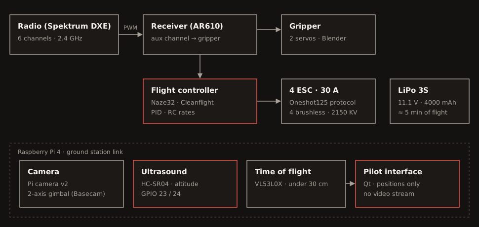
Send the video to the pilot? Beyond 100 metres, latency would have made it useless. So the Raspberry Pi only sends positions and measurements, and a Qt interface, my first in Python, rebuilds the scene: the drone in the middle, the cube moving around it, an altitude gauge, a compass for the cube's angle and a connection gauge. Everything turns from red to green as you get closer.

Measuring altitude
From 100 metres away, you cannot see how high the drone flies. I wired an ultrasound sensor HC-SR04 to the Raspberry Pi, through a voltage divider to protect its inputs, and wrote its Python class: each reading takes ten measurements, drops the extremes and keeps the average, because the sensor sometimes returns an outlier. Below 30 cm, the time-of-flight sensors were to take over.
A test bench with a tape measure checked its accuracy: under 2% error beyond 10 cm, up to 3.60 m (for 4.50 m announced), plenty for the approach to the cube, which happens around one metre.


Stabilising the camera
To spot the cube, the camera must stay parallel to the ground when the drone tilts. It sits on a two-axis gimbal (Basecam), which I tuned with SimpleBGC: for pitch and roll, I set to 0.05, then P raised until the first oscillations, and D raised to damp them, until it no longer helped.

The gripper
My first gripper, modelled in Blender, was to slide on rails to centre itself over the cube. Then the rules changed: the cube would sit in the pilot's zone, and the pilot could move. We needed less precision and more reach. With Fabien, we redesigned it as two jaws, each on its own servo, 3D-printed, then moved closer together after the first tries, when the cube slipped.

Without the time-of-flight sensors, which did not work, the Raspberry Pi could no longer drive the gripper. I soldered the two servos' signals into a single cable, plugged into an auxiliary channel of the receiver: the gripper opens and closes from the radio.
Tuning the flight
That left stability, with Cleanflight: calibrating the accelerometer, setting the motor controllers' protocol to Oneshot125, covering the flight controller, sensitive to light and wind, then adjusting the PIDs and lowering the RC rates so the sticks felt less twitchy. In the end, the drone held steady enough to grab the cube in about thirty seconds.


These three months taught me to write a graphical interface, to design 3D parts and to tune PIDs for real, on the other side of the world, as a team and in another language.